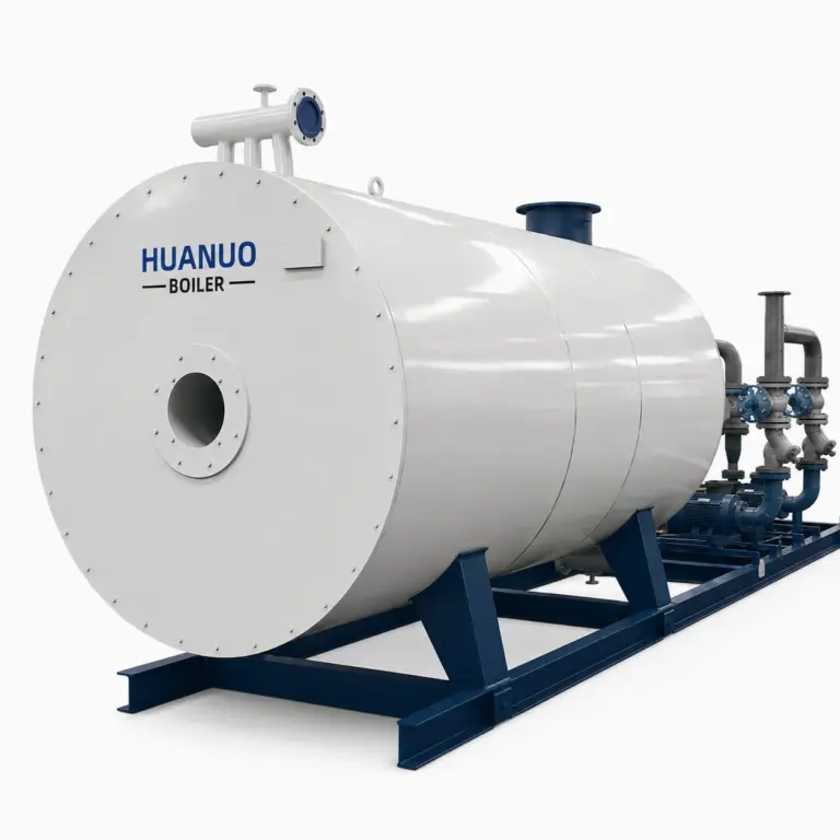
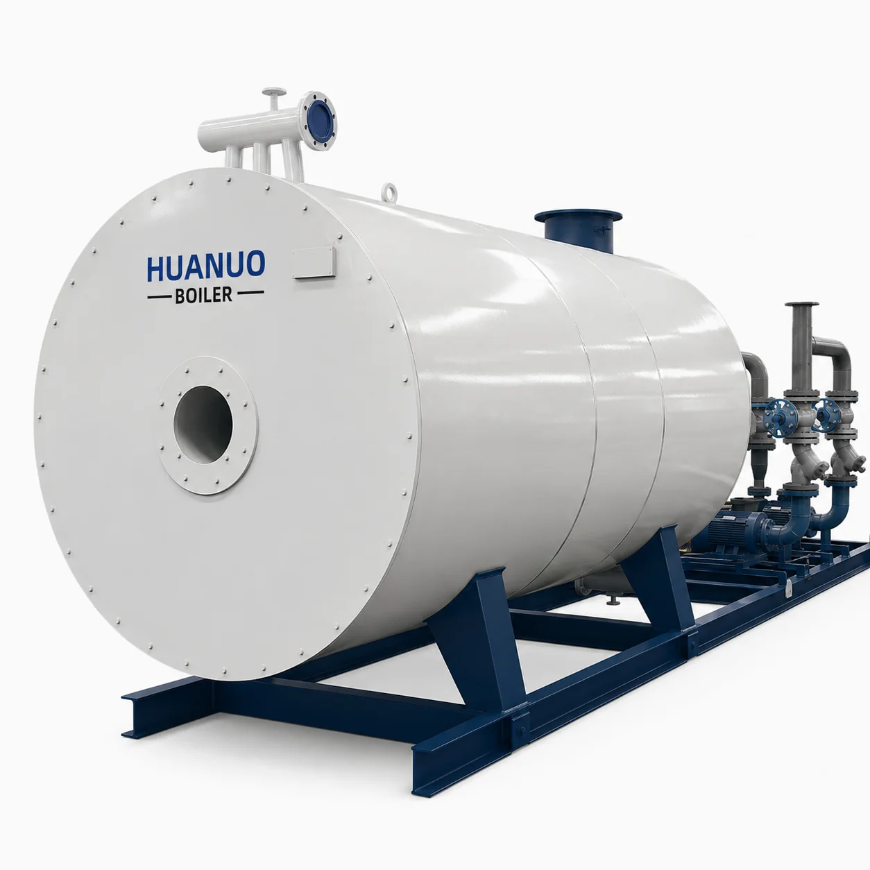
Product Overview
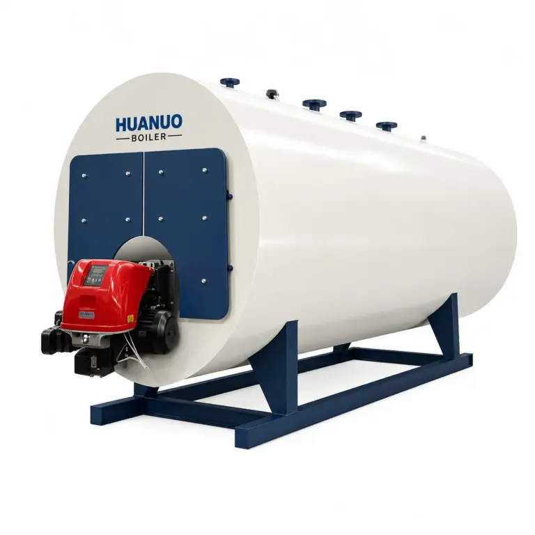
The YY(Q)W Series Gas/Oil-Fired Thermal Oil Heater is designed to provide reliable, high-temperature process heating for industrial applications requiring precise temperature control and efficient thermal energy delivery. Featuring a horizontal, three-pass flue gas structure and a multi-coil heat transfer system, it offers excellent heat transfer performance and accommodates thermal expansion during operation. An optional tail-mounted air preheater recovers exhaust heat to improve energy utilization and reduce fuel consumption. Equipped with an intelligent automatic control system, the heater supports proportional combustion, precise thermal oil temperature regulation, and comprehensive safety interlocks. Its compact structure, dependable operation, and design service life of ≥20 years make it a suitable solution for continuous industrial heating processes.
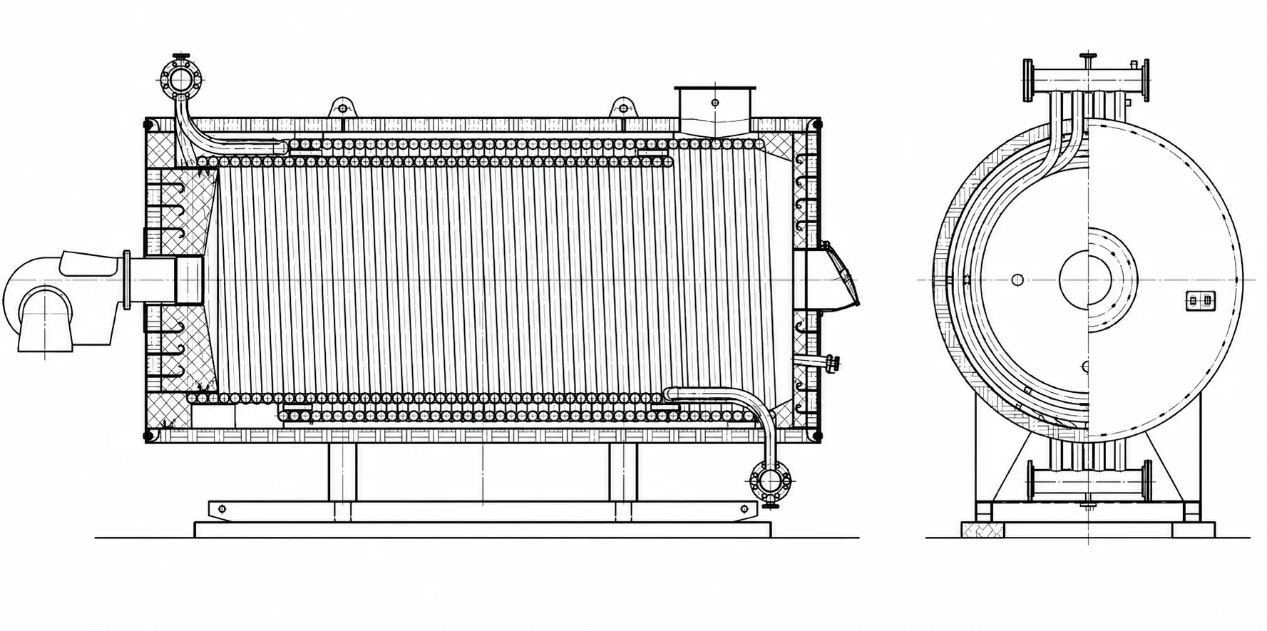
Product Structure Drawing
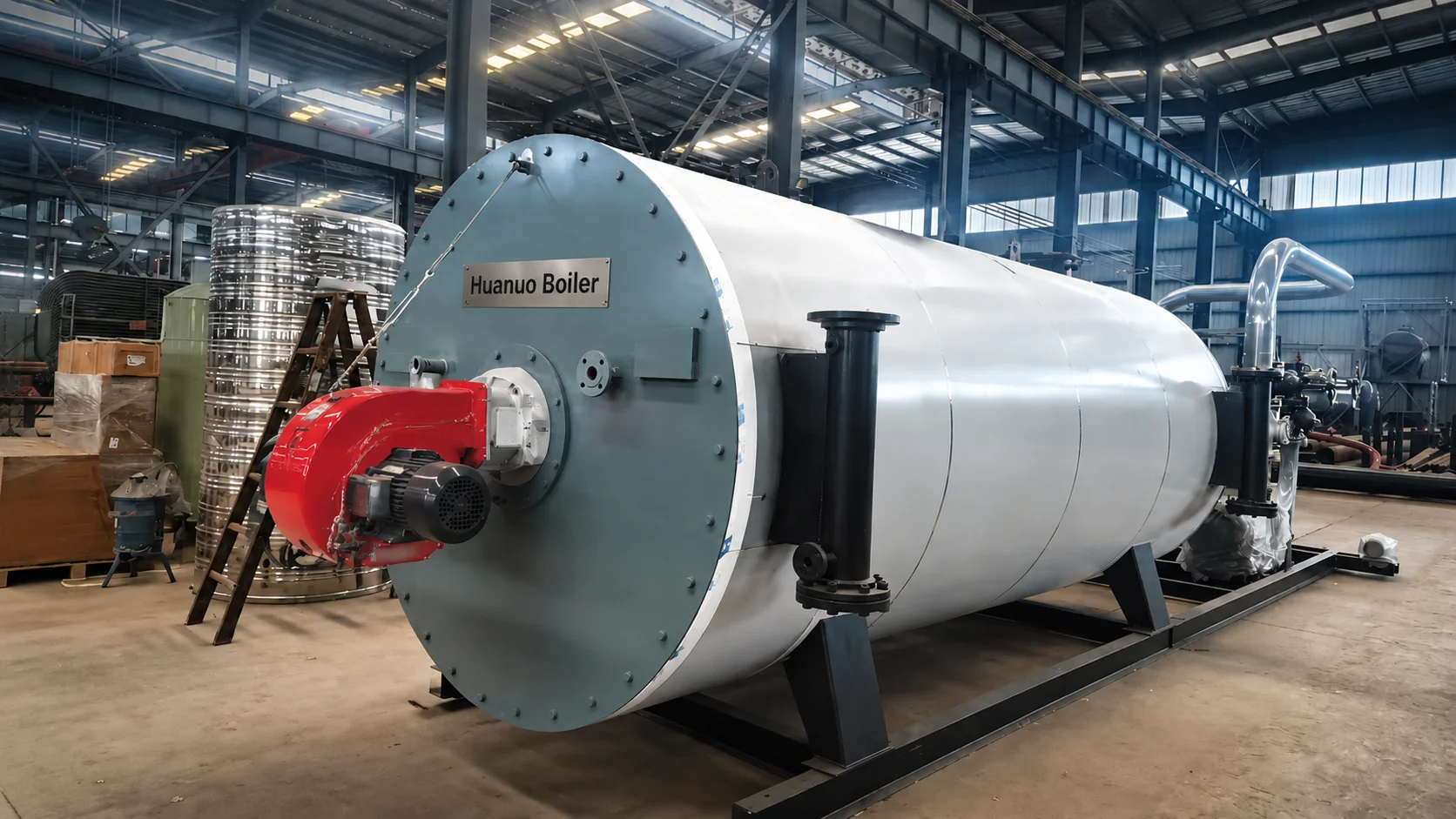
Key Advantages
Delivers thermal energy at temperatures above 300°C while operating at a pressure below 1.0 MPa, making it suitable for industrial processes requiring high-temperature heat without relying on high-pressure steam.
Features a horizontal three-pass flue gas layout with closely arranged inner and outer coils. The multi-coil design accommodates thermal expansion and helps distribute heat more evenly, reducing localized thermal stress.
An optimized flue gas passage and optional tail-mounted air preheater recover exhaust heat and preheat combustion air, improving energy utilization and helping reduce fuel consumption.
Uses Siemens or Delixi electrical components, with an optional HMI touch screen. Automatic proportional combustion and intelligent control help maintain thermal oil temperature within ±1°C under suitable operating conditions.
Features a rear-mounted, automatic-reset explosion-proof door and a multi-stage labyrinth sealing structure. Combined with automatic combustion control and safety interlocks, these features support safe operation and help prevent flue gas leakage.
The integrated cylindrical coil structure and optimized equipment layout reduce the required installation footprint, helping lower boiler room space requirements and initial infrastructure costs.
Typical Applications

Cooking、Pasteurization、Sterilization、Cleaning、Evaporation、Drying

Dyeing、Bleaching、Washing、Sizing、Printing、Drying、Finishing

Reactor Heating、Distillation、 Evaporation、Drying、Stripping、Tank Heating 、Cleaning
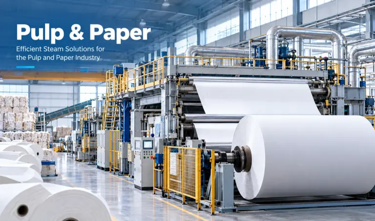
Pulp Cooking、Evaporation、Paper Drying、Starch Preparation、Coating、Tank Heating、Cleaning
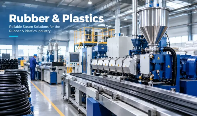
Rubber Vulcanization、Compounding、Mold Heating、Process Water Heating、Equipment Cleaning、Drying

Space Heating、Domestic Hot Water、Campus Heating、Public Building Heating、Industrial Heat Supply、Peak-Load Support
Technical Specifications
| term | model | YY(Q)W-120(Q) | YY(Q)W-240(Q) | YY(Q)W-350(Q) | YY(Q)W-500(Q) | YY(Q)W-700(Q) | YY(Q)W-1000(Q) | YY(Q)W-1200(Q) | YY(Q)W-1400(Q) | YY(Q)W-1800(Q) | YY(Q)W-2100(Q) | YY(Q)W-2400(Q) | YY(Q)W-3000(Q) | YY(Q)W-3500(Q) | YY(Q)W-4700(Q) | YY(Q)W-6000(Q) | YY(Q)W-7000(Q) | YY(Q)W-10000Y(Q) | |
| Rated thermal power | KW | 120 | 240 | 350 | 500 | 700 | 1000 | 1200 | 1400 | 1800 | 2100 | 2400 | 3000 | 3500 | 4700 | 6000 | 7000 | 10000 | |
| Design pressure | MPa | 1.1 | |||||||||||||||||
| Medium outlet temperature | °C | ≤ 350 | |||||||||||||||||
| Heating area | m² | 9.8 | 14.5 | 21.3 | 24 | 40 | 50 | 64.6 | 78.5 | 87 | 94.5 | 106.2 | 163 | 205.2 | 254.3 | 325 | 410 | 520 | |
| Fuel | light oil/LNG/CG | light oil/heavy oil/LNG/CG | |||||||||||||||||
| Fuel | Light oil | Kg/h | 12 | 25 | 37 | 52 | 69 | 100 | 120 | 140 | 180 | 210 | 244 | 300 | 350 | 470 | 580 | 680 | 970 |
| LNG | Nm³/h | 15 | 30 | 44 | 63 | 83 | 120 | 145 | 170 | 220 | 260 | 296 | 365 | 425 | 570 | 700 | 810 | 1160 | |
| Gas pressure | LNG | mbar | 30–100 | 50–150 | 50–200 | 100–300 | |||||||||||||
| The total electric power equipment | Light oil fired | KW | 4 | 8 | 10 | 10 | 18 | 26 | 26 | 26 | 46 | 46 | 46 | 66 | 78 | 98 | 115 | 115 | 132 |
| LNG fired | KW | 4 | 8 | 10 | 10 | 18 | 25 | 26 | 26 | 46 | 46 | 46 | 64 | 72 | 95 | 110 | 110 | 128 | |
| Furnace oil content | m³ | 0.1 | 0.15 | 0.25 | 0.3 | 0.5 | 0.8 | 0.85 | 1.1 | 1.2 | 1.7 | 1.9 | 3.5 | 3.8 | 4.2 | 6.2 | 7 | 10.5 | |
| Boiler dimensions | mm | 1600 × 1020 × 1520 | 1930 × 1230 × 1868 | 2100 × 1390 × 2055 | 2200 × 1390 × 2055 | 3240 × 1470 × 2260 | 3300 × 1670 × 2486 | 3830 × 1770 × 2587 | 4145 × 1900 × 2786 | 4600 × 2000 × 3045 | 5020 × 2050 × 3080 | 5080 × 2200 × 3180 | 5983 × 2420 × 3404 | 6555 × 2470 × 3634 | 7285 × 2570 × 3760 | 7800 × 3050 × 3800 | 8200 × 3050 × 3800 | 10000 × 3500 × 4000 | |
| Boiler transport weight | T | 1.5 | 2 | 2.58 | 3 | 3.7 | 5 | 5.8 | 6.7 | 7.8 | 8.8 | 9.8 | 15.5 | 17.8 | 21.5 | 25 | 27.5 | 32 | |
| Oil inlet | DN | 45 | 65 | 80 | 100 | 125 | 150 | 200 | 250 | 300 | |||||||||
| Oil outlet | DN | 45 | 65 | 80 | 100 | 125 | 150 | 200 | 250 | 300 | |||||||||
| Expansion tank | m³ | 0.5 | 1.5 | 2 | 2.5 | 3 | 5 | 6 | |||||||||||
| Storage tank | m³ | 1 | 2.5 | 4 | 5 | 8 | 10 | 15 | |||||||||||
| Chimney ø | mm | 200 | 280 | 350 | 400 | 500 | 600 | 700 | 800 | ||||||||||