
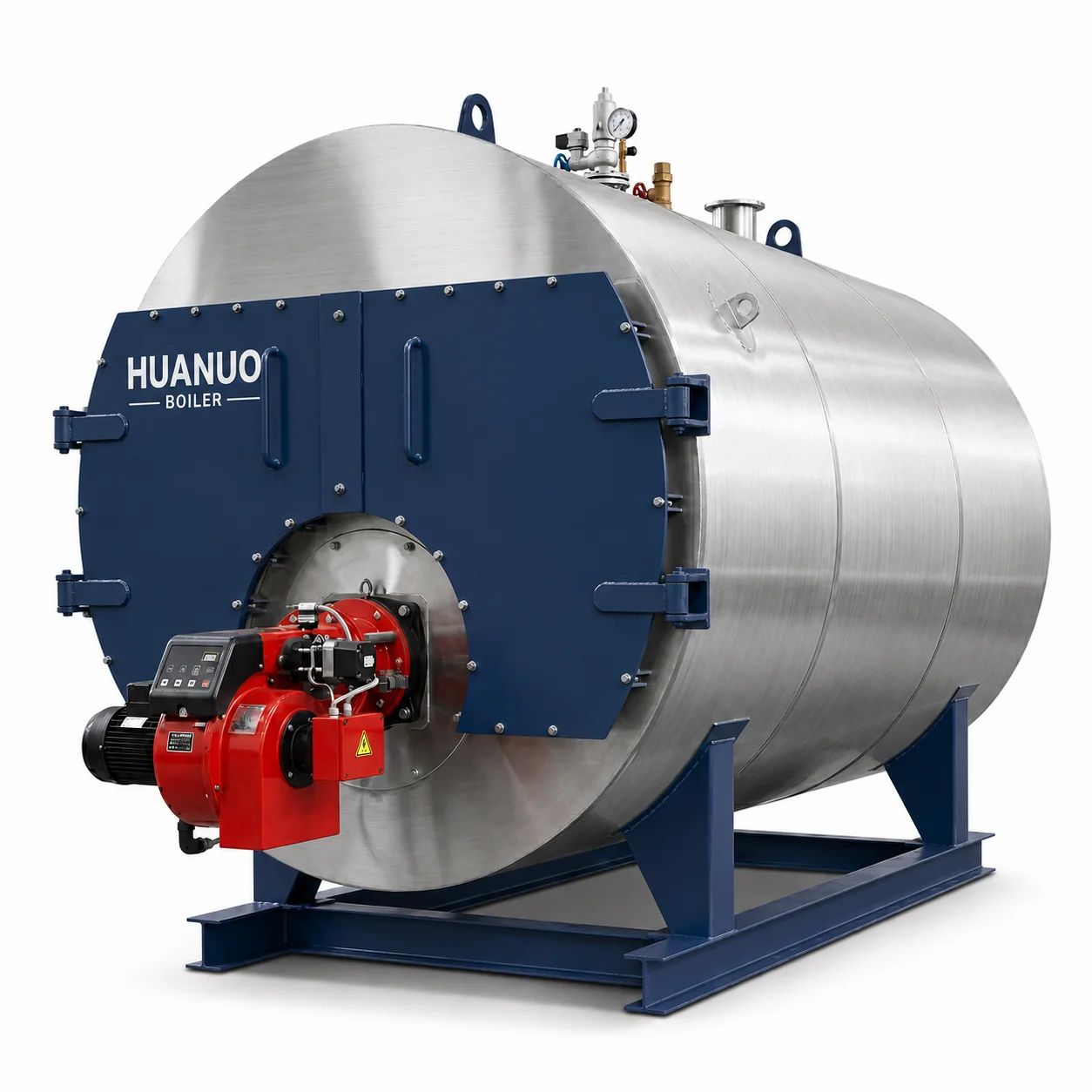
Product Overview
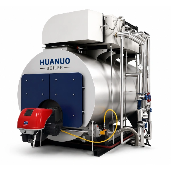
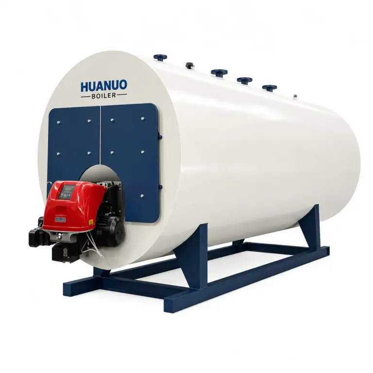
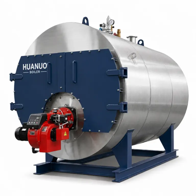
The WNS Series Industrial Gas/Oil-Fired Pressurized Hot Water Boiler is designed to deliver reliable and efficient hot-water heating for industrial and commercial applications. Featuring a horizontal, three-pass, full wet-back fire-tube structure, a large-diameter corrugated furnace, and threaded smoke tubes, it provides effective heat transfer and stable thermal output under varying load conditions. Its optimized anti-boiling water circulation system, automated combustion control, and comprehensive safety interlocks support reliable operation and help reduce maintenance requirements. Available for natural gas, LPG, diesel, and heavy oil, the series offers rated heating capacities from 0.7 to 14 MW, thermal efficiency of at least 95%, and a design service life exceeding 20 years.
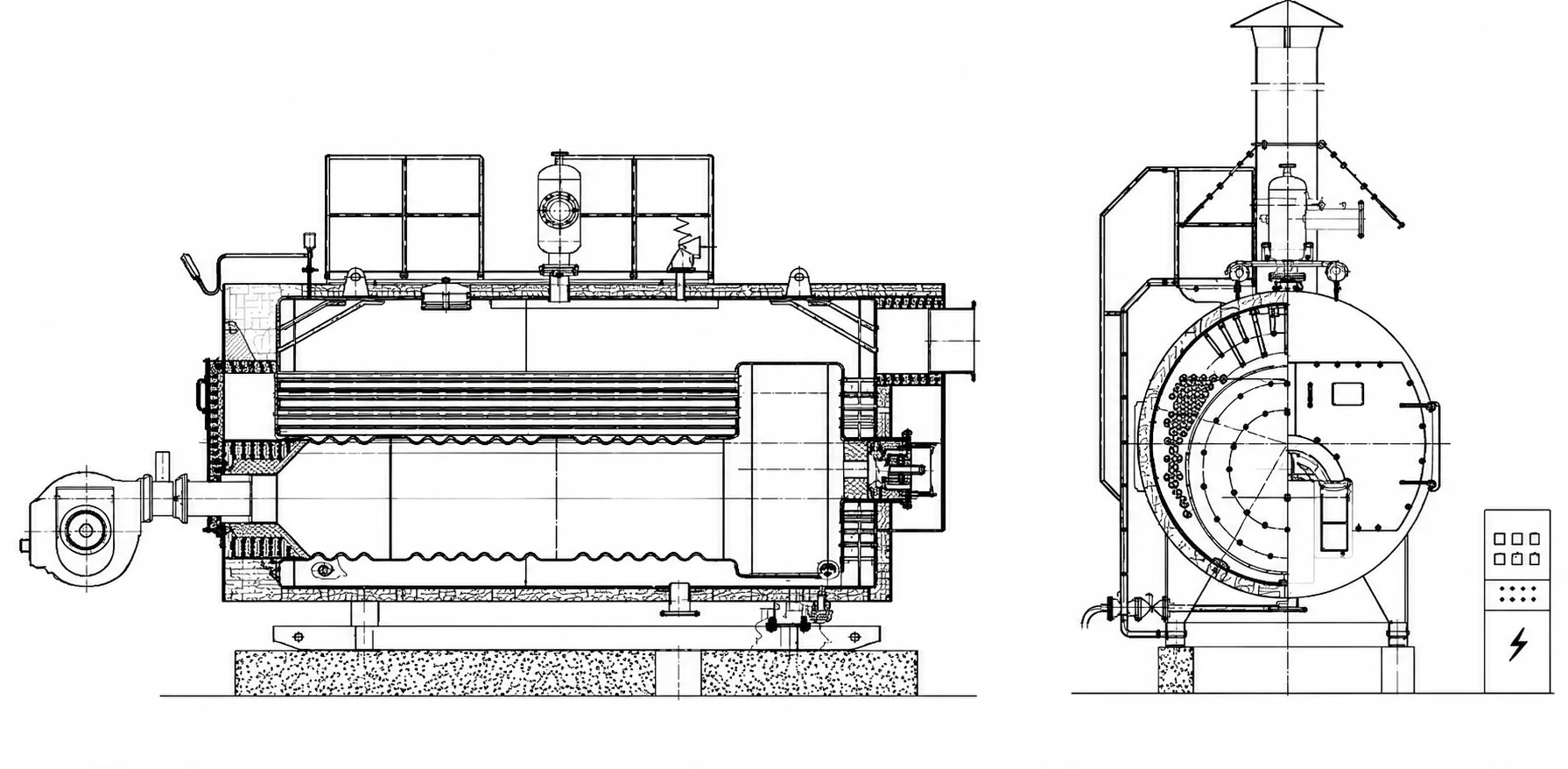
Product Structure Drawing
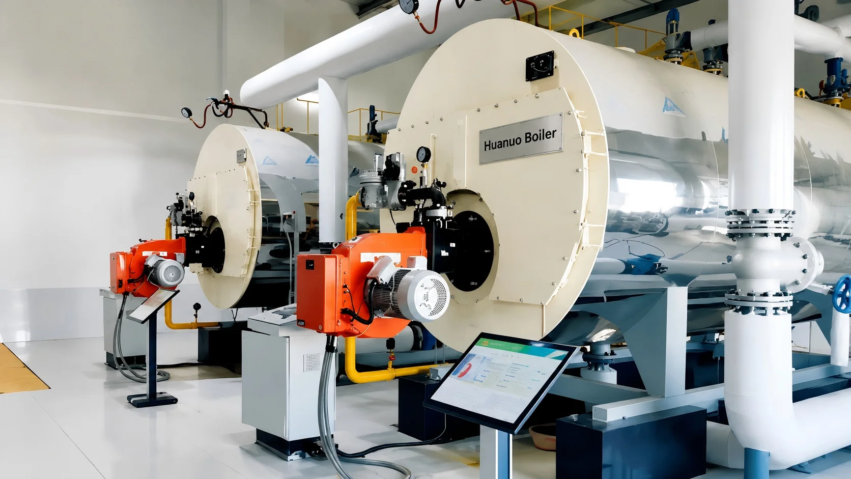
Key Advantages
Features a horizontal, three-pass fire-tube design with full butt-welded construction, a corrugated furnace, and threaded smoke tubes to enhance heat transfer and accommodate thermal expansion.
The optimized return-water arrangement (Patent No. ZL 2014 2 0505874.8) enhances water-side circulation in high-temperature zones, helping prevent subcooled boiling and reduce the risk of tube plate and tube-end cracking.
The large-diameter boiler shell and substantial water volume provide high thermal storage capacity, supporting stable heat output and responsive operation under changing heating demands.
Integrates water-level monitoring, low-water burner cut-off, electrical leakage protection, and overpressure and overtemperature alarms. A rear-mounted, automatic-reset explosion-proof door provides additional furnace protection.
Double-opening front and rear smoke-box doors feature reusable, multi-stage labyrinth seals to help prevent flue-gas leakage. Top manholes and bottom handholes facilitate internal inspection, cleaning, and maintenance.
Uses Siemens or Delixi electrical components, as configured, to support automatic combustion adjustment, water-level control, and real-time fault diagnostics for reliable, continuous operation with minimal manual intervention.
Typical Applications

Cooking、Pasteurization、Sterilization、Cleaning、Evaporation、Drying

Dyeing、Bleaching、Washing、Sizing、Printing、Drying、Finishing

Reactor Heating、Distillation、 Evaporation、Drying、Stripping、Tank Heating 、Cleaning

Pulp Cooking、Evaporation、Paper Drying、Starch Preparation、Coating、Tank Heating、Cleaning

Rubber Vulcanization、Compounding、Mold Heating、Process Water Heating、Equipment Cleaning、Drying

Space Heating、Domestic Hot Water、Campus Heating、Public Building Heating、Industrial Heat Supply、Peak-Load Support
Technical Specifications
| Item | Model | WNS0.35 | WNS0.7 | WNS1.05 | WNS1.4 | WNS2.1 | WNS2.8 | WNS3.5 | WNS4.2 | WNS5.6 | WNS7 | WNS8.4 | WNS10.5 | WNS14 | |
| Rated power | MW | 0.35 | 0.7 | 1.05 | 1.4 | 2.1 | 2.8 | 3.5 | 4.2 | 5.6 | 7 | 8.4 | 10.5 | 14 | |
| Rated pressure | MPa | 0.7/1.0 | 0.7/1.0/1.25 | ||||||||||||
| Rated inlet water temperature | °C | 70 | 70 | ||||||||||||
| Rated outlet water temperature | °C | 95 or 115 | 95/115/130 | ||||||||||||
| Heating area | m² | 16 | 24.6 | 40 | 53 | 79 | 103 | 122 | 140 | 183 | 251 | 285 | 375 | 448 | |
| Fuel | Heavy oil/light oil, natural gas/LPG/city gas | ||||||||||||||
| Fuel consumption | Light oil | kg/h | 33.3 | 68.7 | 102 | 136 | 203 | 208 | 339 | 407 | 539 | 671 | 806 | 1010 | 1380.33 |
| Natural gas | Nm³/h | 40.2 | 78 | 118 | 157 | 240 | 316 | 386 | 472 | 615 | 760 | 915 | 1145 | 1598.44 | |
| Power | Light oil | kw | 1.1 | 2.5 | 2.6 | 4 | 4.5 | 9 | 9 | 12 | 17.5 | 25 | 45 | 52.7 | / |
| Gas | kw | 1.1 | 2.5 | 2.6 | 4 | 6.5 | 6.5 | 9 | 12 | 13.5 | 21 | 28 | 37 | / | |
| Max. transportation weight | t | 2.8 | 4.6 | 6.2 | 6.9 | 9.9 | 11.5 | 13.4 | 15.3 | 20.2 | 22.9 | 25.8 | 35.6 | 40 | |
| Full water capacity | m³ | 1.2 | 3.2 | 4.6 | 5.6 | 6.8 | 9 | 10.5 | 11.4 | 18.4 | 20.4 | 23.1 | 30.2 | 40.5 | |
| Base frame (A×B) | m | 2.2×0.93 | 2.3×1.3 | 2.6×1.6 | 3.3×1.6 | 3.3×1.8 | 4.3×1.8 | 4.3×2 | 4.4×2 | 5.1×2 | 5.8×2 | 6.4×2 | 7.2×2.5 | 8×2.5 | |
| Max. overall dimension (L×W×H) | m | 3.45 × 1.5 × 2.4 | 4.13 × 2.25 × 2.9 | 4.63 × 2.43 × 3.34 | 5.03 × 2.765 × 3.34 | 5.5 × 3.1 × 3.62 | 6.2 × 3.125 × 3.62 | 6.1 × 3.3 × 3.96 | 6.5 × 3.3 × 4.05 | 7.8 × 3.6 × 4.5 | 8.72 × 3.6 × 4.5 | 8.97 × 3.6 × 4.5 | 10.44 × 4.1 × 5.2 | 10.64 × 4.1 × 5.2 | |
| Water inlet valve diameter | DN mm | DN50 | DN50 | DN50 | DN50 | DN50 | DN65 | DN80 | DN100 | DN125 | DN125 | DN150 | DN150 | DN200 | |
| Water outlet valve diameter | DN mm | / | / | / | / | / | / | / | / | / | / | DN40 | / | DN50 | |
| Safety valve diameter | DN mm | DN32 | DN25 | DN25 | DN32 | DN32 | DN40 | DN40 | DN50 | DN50 | DN50 | DN50 | DN50 | DN65 | |
| Safety valve | Interface | DN mm | DN40 | DN40 | DN40 | DN40 | DN40 | DN40 | DN40 | DN50 | DN50 | DN65 | DN80 | DN80 | DN100 |
| Blowdown port | DN mm | DN50 | DN50 | DN50 | DN50 | DN50 | DN50 | DN50 | DN65 | DN65 | DN80 | DN100 | DN100 | DN125 | |
| Drain valve diameter | DN mm | DN40 | DN40 | DN40 | DN40 | DN40 | DN40 | DN40 | DN40 | DN40 | DN50 | DN50 | DN50 | DN50 | |
| Fuel oil port | Oil inlet | mm | 8 | 13 | 13/20 | 13/20 | 13/20 | 20 | 20 | 25 | 25 | 25 | 25 | 25 | 25 |
| Oil return | mm | 8 | 13 | 13 | 13 | 13 | 20 | 20 | 25 | 25 | 25 | 25 | 25 | 25 | |
| Gas supply port | DN mm | According to gas supply pressure | |||||||||||||
| Chimney diameter | Φ mm | 280 | 280 | 400 | 400 | 500 | 500 | 600 | 600 | 700 | 700 | 800 | 900 | 1000 | |